
You are using an out of date browser. It may not display this or other websites correctly.
You should upgrade or use an alternative browser.
You should upgrade or use an alternative browser.
Gamecube to Game Boy Micro Cable - Instructions in here
- Thread starter Troz1820
- Start date
Hi,
I finally managed to solder two GBM-GC cables using the method for the original GBA-GC cable described in the first post. They work perfectly, thanks a lot.
Anyways, right now I look for a decent case to fit the uncovered electronics but most importantly I wonder how I'm gonna isolate the cables and pins appropriately.
Have you any ideas what I could use to prevent the connections from touching each other? I think shrink tubing wouldn't be a good idea since the cables are already soldered. In the first post it seems as if he had used hot glue or something similar to fix the problem....
Thanks for the help!
j.m.ratkos
CAGiversary!
- Feedback
- 1 (100%)
breathing some life back into this thread:
if anyone is still looking for official game boy micro link cables, this site appears to have them in stock. I've ordered a few and will reply to this thread again once I receive them to confirm that they are in fact, the official cables.
http://www.vpgames.com/p-14592-offi...nects-two-gameboy-micro-systems-together.aspx
edit:
17 sep 2011
received the nintendo micro link cables today and I can confirm that they are the official nintendo cables.")
if anyone is still looking for official game boy micro link cables, this site appears to have them in stock. I've ordered a few and will reply to this thread again once I receive them to confirm that they are in fact, the official cables.
http://www.vpgames.com/p-14592-offi...nects-two-gameboy-micro-systems-together.aspx
edit:
17 sep 2011
received the nintendo micro link cables today and I can confirm that they are the official nintendo cables.
Last edited by a moderator:
Shadow_Zero
CAGiversary!
I'm looking for one of these cables as well. I don't see myself soldering this, so anyone who can help out (or knows someone who can)?
juanchopancho
CAG Veteran
hi everybody,i found this post because i was looking for a home-made link cable,i have two chargers for gb micro and i want to mike a conversion. watching some of your images i had an idea of how make one:
2 vdd 3.3 -----7gnd
3 so ----------- 4si
4 si------------ 3 so
5 sd--------- --5 sd
6 sc------------6 sc
7 gnd--------- 2vdd 3.3v
what do you think about?.
its possible to make the homemade link wire ?? thaks and sorry for my bad english
2 vdd 3.3 -----7gnd
3 so ----------- 4si
4 si------------ 3 so
5 sd--------- --5 sd
6 sc------------6 sc
7 gnd--------- 2vdd 3.3v
what do you think about?.
its possible to make the homemade link wire ?? thaks and sorry for my bad english
Shadow_Zero
CAGiversary!
PM'd
EDIT:
I'm pondering to give it a shot myself. What I'm wondering at the moment is if the guide from Troz1820 here is the same as the one from TCCPhreak (http://www.mksmks.de/technical/gbmtocube.htm )? It mentions:
EDIT:
I'm pondering to give it a shot myself. What I'm wondering at the moment is if the guide from Troz1820 here is the same as the one from TCCPhreak (http://www.mksmks.de/technical/gbmtocube.htm )? It mentions:
but the soldering seems different, is it not?WAIT! We're connecting the GBA/GBM to a Gamecube (which has it's own power source) and expect the cable to be powered from the small battery-driven device? Are we crazy? Why not use the Gamecube for it?I tried. It worked. So if there is a reason, let's ignore it.
Last edited by a moderator:
Shadow_Zero
CAGiversary!
Ok, I've got my GBA link cable open: pic1 - overview
(which is the same as the last one mentioned in TCCPhreak's article
pic2 - closeup downside
pic3 - closeup upper side
Where exactly do I cut the GBM cable? Is that here?
pic4 - gbm plug
(which is the same as the last one mentioned in TCCPhreak's article
pic2 - closeup downside
pic3 - closeup upper side
Where exactly do I cut the GBM cable? Is that here?
pic4 - gbm plug
Last edited by a moderator:
[quote name='Shadow_Zero'] I'm pondering to give it a shot myself. What I'm wondering at the moment is if the guide from Troz1820 here is the same as the one from TCCPhreak [/QUOTE] The main stuff is the same in my guide and in the one from Troz1820 - after all, he started my interest in that stuff. I only started trying other stuff as those "original" cables are becoming rare and always have been expensive (the GBM-link cables as well as the GBA-Cube-cables). As most cheaper GBM-link-cables don't include a wire for providing external hardware with power, I had to try using the gamecube for power. I believe that this is the main difference between our guides: He uses the original Nintendo GBM-link-cable and can use the power from there; I use other GBM-link-cables and need to bridge a VCC-connection on the GBA-Cube-cable. [quote name='Shadow_Zero'] Ok, I've got my GBA link cable open: pic1 - overview
(which is the same as the last one mentioned in TCCPhreak's article [/QUOTE] Yes.. that seems to be the "Neue Version". Was your vendor able to tell you what the second link port is for? [quote name='Shadow_Zero'] Where exactly do I cut the GBM? Is that here?[/QUOTE] What do you mean by "cutting the GBM"? What cable do you have on GBM-side? The pads 1,3 and 5 need to be connected to your GBM(cable). If your GBM-cable provides power, connect that wire to the pad 6, else bridge the Cube-VCC (marked as such) to pad 6. In the later case I strongly recommend desoldering the original wires (so you'll never connect that cable to a GBA). Even if you don't, never connect GBM and GBA at the same time with the same cable.. Regards, TCC
(which is the same as the last one mentioned in TCCPhreak's article [/QUOTE] Yes.. that seems to be the "Neue Version". Was your vendor able to tell you what the second link port is for? [quote name='Shadow_Zero'] Where exactly do I cut the GBM? Is that here?[/QUOTE] What do you mean by "cutting the GBM"? What cable do you have on GBM-side? The pads 1,3 and 5 need to be connected to your GBM(cable). If your GBM-cable provides power, connect that wire to the pad 6, else bridge the Cube-VCC (marked as such) to pad 6. In the later case I strongly recommend desoldering the original wires (so you'll never connect that cable to a GBA). Even if you don't, never connect GBM and GBA at the same time with the same cable.. Regards, TCC
Shadow_Zero
CAGiversary!
Ah, that should have been "Where exactly to cut the GBM cable" (forgot to type "cable"). So where exactly do I cut the GBM cable open?
Since it's a 3rd party cable I don't think it's got the power wire, so I'll need to desolder the original wires on the GBA-GC cable and bridge the Cube-VCC.
And no, I've never heard what the second link port is for. I always thought it was a GBA link port, but never gave it much though. Perhaps to hook 1 GBA to the Cube and link a second GBA so 1 player can play on the tv (with Gameboy Player) and the other on the GBA or something?
[quote name='Shadow_Zero']Ah, that should have been "Where exactly to cut the GBM cable" (forgot to type "cable"). So where exactly do I cut the GBM cable open?
[/QUOTE]
The cable should be exactly the same at any point between the connectors. Usually I try to cut in the middle, so I have two parts with equally long cable.
[quote name='Shadow_Zero']
And no, I've never heard what the second link port is for. I always thought it was a GBA link port, but never gave it much though.
[/QUOTE]
AFAIR I checked the wiring and it's not just a passthrough (allowing to link to another GBA or to the cube without taking off the plug, first).
[quote name='Shadow_Zero']
Perhaps to hook 1 GBA to the Cube and link a second GBA so 1 player can play on the tv (with Gameboy Player) and the other on the GBA or something?[/QUOTE]
As the Gameboy Player mainly is another GBA that'd be three GBAs to play one game? Why should people need this linkage just to play a game?
The fun thing about this port is that nobody seems to know what it is for. I found no info on the internet and the seller couldn't answer me that question, either.
btw:
The Gameboy Player is so much a GBA, that you can use it to connect to another Cube (or older Wii) via the GBA-Cube-cable. The manual states that this is impossible but we played FFCC with three GBAs and a Cube connected to another Cube.
Someone even was crazy enough to have three Gamecubes with Gameboy Players connected to one Wii.
Even more crazy: He thought that playing with Wavebirds was the ridiculous part of it: http://www.youtube.com/watch?v=zivqno6zWLY
Regards,
TCC
[/QUOTE]
The cable should be exactly the same at any point between the connectors. Usually I try to cut in the middle, so I have two parts with equally long cable.
[quote name='Shadow_Zero']
And no, I've never heard what the second link port is for. I always thought it was a GBA link port, but never gave it much though.
[/QUOTE]
AFAIR I checked the wiring and it's not just a passthrough (allowing to link to another GBA or to the cube without taking off the plug, first).
[quote name='Shadow_Zero']
Perhaps to hook 1 GBA to the Cube and link a second GBA so 1 player can play on the tv (with Gameboy Player) and the other on the GBA or something?
[/QUOTE]As the Gameboy Player mainly is another GBA that'd be three GBAs to play one game? Why should people need this linkage just to play a game?
The fun thing about this port is that nobody seems to know what it is for. I found no info on the internet and the seller couldn't answer me that question, either.
btw:
The Gameboy Player is so much a GBA, that you can use it to connect to another Cube (or older Wii) via the GBA-Cube-cable. The manual states that this is impossible but we played FFCC with three GBAs and a Cube connected to another Cube.
Someone even was crazy enough to have three Gamecubes with Gameboy Players connected to one Wii.
Even more crazy: He thought that playing with Wavebirds was the ridiculous part of it: http://www.youtube.com/watch?v=zivqno6zWLY
Regards,
TCC
Last edited by a moderator:
Shadow_Zero
CAGiversary!
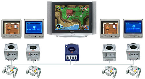
Yeah, I once did the 5 tv's + Gamecubes setup for Four Swords. Insane, but fun
http://www.youtube.com/watch?gl=NL&hl=nl&v=3NNZ65Z0IyE (not my video)
3 GBA's to play 1 game? I meant:
- 1 GC + GB Player + 'Neue version' cable GC-GBA link cable + multiplayer game
- 1 GBA + GBA link cable + same multiplayer game
The GC-Link cable blocks the GBA link port, but due to the extra connection there can be a link connection.
But that's all speculative. The port isn't even straight, so it's hard to plugin a link cable to start with (and you mentioned it isn't passthroughed).
Last edited by a moderator:
Shadow_Zero
CAGiversary!
[quote name='TCCPhreak']The pads 1,3 and 5 need to be connected to your GBM(cable). If your GBM-cable provides power, connect that wire to the pad 6, else bridge the Cube-VCC (marked as such) to pad 6. In the later case I strongly recommend desoldering the original wires (so you'll never connect that cable to a GBA). Even if you don't, never connect GBM and GBA at the same time with the same cable.. Regards, TCC[/QUOTE]
Instead of desoldering the wires, can I also cut them and solder the GBM wires to them?
Instead of desoldering the wires, can I also cut them and solder the GBM wires to them?
Shadow_Zero
CAGiversary!
Ok, I've got the GBM cable open now. I have to re-read everything, but I'm afraid I'm a bit stuck then, since it's not an official GBM link cable and I have no clue which wire is which pin...
GBM link cable
Any advice on how to figure that out?
GBM link cable
Any advice on how to figure that out?
Last edited by a moderator:
[quote name='Shadow_Zero']Instead of desoldering the wires, can I also cut them and solder the GBM wires to them?[/QUOTE]
I guess you could.. but I always considered wiring to the pads easier than soldering wires together, using shrinking tube etc.
[quote name='Shadow_Zero']
Ok, I've got the GBM cable open now. I have to re-read everything, but I'm afraid I'm a bit stuck then, since it's not an official GBM link cable and I have no clue which wire is which pin...
[/QUOTE]
I think your best choice is to take an ohm-meter (or anything else that beeps when the testing pins are electrically connected) and then check with the pins on the connector plug. If you somewhere get a gbm-link-plug (e.g. broken GBM; link-cable with box), you could build a breakout-box allowing to measure at the bananaplugs.
TCC
Shadow_Zero
CAGiversary!
[quote name='TCCPhreak']I use other GBM-link-cables and need to bridge a VCC-connection on the GBA-Cube-cable. Yes.. that seems to be the "Neue Version". What cable do you have on GBM-side? The pads 1,3 and 5 need to be connected to your GBM(cable). If your GBM-cable provides power, connect that wire to the pad 6, else bridge the Cube-VCC (marked as such) to pad 6. In the later case I strongly recommend desoldering the original wires (so you'll never connect that cable to a GBA). Even if you don't, never connect GBM and GBA at the same time with the same cable.. Regards, TCC[/QUOTE]
Ok, someone helped me out with an ohm meter, and this is the result of my 4-wired 3rd party GBM link cable:
brown wire = pin 6 (Ground)
green wire = pin 5 (Serial Clock)
blue wire = pin 4 (Serial Data)
white wire = pin 3 (Serial In)
Hmmmz, that doesn't sound logical. Perhaps it should be the other way around (then I have wrong schematics or I'm reading them wrong; using the one from http://www.mksmks.de/technical/gbmtocube.htm):
brown wire = pin 1 (Power)
green wire = pin 2 (Serial Out)
blue wire = pin 3 (Serial In)
white wire = pin 3 (Serial Data)
http://www.mksmks.de/technical/gbmtocube.htm states for the 'Neue' gc-gba cable:
1 (red) = GND (GBA pin 6)
3 (brown) = Serial Out (GBA pin 2)
5 (blue) = Serial In (GBA pin 3)
6 (white) = Power (Cube power)
EDIT:
The schematics seem to be right, so then I don't understand the wiring of this GBM link cable. Anyone a suggestion?
Last edited by a moderator:
[quote name='Shadow_Zero']Ok, someone helped me out with an ohm meter, and this is the result of my 4-wired 3rd party GBM link cable:
brown wire = pin 6 (Ground)
green wire = pin 5 (Serial Clock)
blue wire = pin 4 (Serial Data)
white wire = pin 3 (Serial In)
[/QUOTE]
Colors can be different from cable to cable. So don't worry too much if those wire colors don't match any from a given other cable.
I remembered something else about this cable stuff (it's been a long time. Sorry for not thinking about this, earlier): The connection between GBA and Gamecube only needs four wires in many cables 1,2,3,6 (with 1 being power and being replaced by the cube-connection).
On the other hand, wire 2 (Serial Out) is really needed for communicating with the gamecube.
If you only got a 2-player-link-cable: cheap cables often don't have wire 2. Master and Slave are hard-coded into the wire with 3(SerialIn) and 6(GND) crossed on the "master"(p1) side. I believe that's how the GBA "knows" that it is master - whereas the slave "sees" a real signal on SerialIn (Master.SerialOut).
Take a look at the "Link 4 Spieler"-image, ignore everything after Sp.2 ("Spieler 2" = "Player2" = slave) and imagine you want to produce a very cheap cable - no need to include Sp2.SO (wire2) anywhere.
Sadly, this means that many cheap 2-player-link-cables cannot be used for the GBA-conversion: You cannot access Master.3 (it's connected to GND); you cannot access Slave.2 (it's not an outside wire).
Your best choice is to search for 4-player-cables. At minimum, the plugs for Player2 and Player3 will have all necessary wires.
Also, at that point, capitalism strikes again and having the same plug four times is cheaper than a 2,1,1 distribution. I believe that all of my GBM-four-player-cables had all four plugs the same and usable for conversion.
Regards,
TCC
Shadow_Zero
CAGiversary!
Ah man, I thought I was so close, now we're discovering my GBM link cable doesn't have pin 2 wired?
Maybe I can try this mod: http://destudenten.site50.net/DS6/index.php/projecten/gbmnrngc/gamecube-kabel heh
(also found him on GBATemp: http://gbatemp.net/threads/gameboy-micro-to-ngc.231999/ )
I know the colours don't say anything, I listed them, in any case, for knowledgebase sake (if anyone else has this cable and would like to know).
Or does anyone here have a plug/cable leftover? =)
EDIT:
Seems like some Chinese factory decided to make the 'official' cables again, they're all over eBay, for cheap prices: http://www.ebay.co.uk/itm/ORIGINAL-...LI-/330742947552?ssPageName=ADME:L:OC:NL:3160
Last edited by a moderator:
[quote name='Shadow_Zero']Ah man, I thought I was so close, now we're discovering my GBM link cable doesn't have pin 2 wired?
[/QUOTE]
Sorry for not remembering this earlier. It really has been a long time but this was the main reason for ordering the 4-player-cables. I hoped to get at least two usable plugs but found myself with four of them.
To be sure that the cable is not usable, you could check the other part for whether the two pins are linked together.
[quote name='Shadow_Zero']
Maybe I can try this mod: http://destudenten.site50.net/DS6/index.php/projecten/gbmnrngc/gamecube-kabel
[/QUOTE]
From what I can read (somehow, the google translation is less readable than the original nederlandsk), the main idea is scraping off the plastic to get to the plug directly and then soldering the wires to the plug directly. I never quite managed to do this without completely wasting the plug but as a "last resort" it should always work.
[quote name='Shadow_Zero']
Or does anyone here have a plug/cable leftover? =)
[/QUOTE]
I still have some parts left but I guess the shipping from germany might be more than getting a suitable cable from another source.
[quote name='Shadow_Zero']
EDIT:
Seems like some Chinese factory decided to make the 'official' cables again, they're all over eBay, for cheap prices: http://www.ebay.co.uk/itm/ORIGINAL-...LI-/330742947552?ssPageName=ADME:L:OC:NL:3160[/QUOTE]
I'm not sure whether this is a real rebuilt of the original cables or simple a cheap two-player-cable with some (non-electronic) black block in the middle. If someone tried buying this, I would be interested in more information. I think I'll have to test this out.
They ship to germany for free. I'll try one and report back once I have more info.
Regards,
TCC
[/QUOTE]
Sorry for not remembering this earlier. It really has been a long time but this was the main reason for ordering the 4-player-cables. I hoped to get at least two usable plugs but found myself with four of them.
To be sure that the cable is not usable, you could check the other part for whether the two pins are linked together.
[quote name='Shadow_Zero']
Maybe I can try this mod: http://destudenten.site50.net/DS6/index.php/projecten/gbmnrngc/gamecube-kabel
[/QUOTE]
From what I can read (somehow, the google translation is less readable than the original nederlandsk), the main idea is scraping off the plastic to get to the plug directly and then soldering the wires to the plug directly. I never quite managed to do this without completely wasting the plug but as a "last resort" it should always work.
[quote name='Shadow_Zero']
Or does anyone here have a plug/cable leftover? =)
[/QUOTE]
I still have some parts left but I guess the shipping from germany might be more than getting a suitable cable from another source.
[quote name='Shadow_Zero']
EDIT:
Seems like some Chinese factory decided to make the 'official' cables again, they're all over eBay, for cheap prices: http://www.ebay.co.uk/itm/ORIGINAL-...LI-/330742947552?ssPageName=ADME:L:OC:NL:3160[/QUOTE]
I'm not sure whether this is a real rebuilt of the original cables or simple a cheap two-player-cable with some (non-electronic) black block in the middle. If someone tried buying this, I would be interested in more information. I think I'll have to test this out.
They ship to germany for free. I'll try one and report back once I have more info.
Regards,
TCC
Shadow_Zero
CAGiversary!
I'm in the Netherlands btw, and I (also I guess) ordered two of those Chinese cables
Scraping off the plastic is a helluvajob, and I even cut my finger when I used a craft knife meh

But I'm almost there:
http://www.myspace.com/shadow_z80/photos/albums/gbm/1657350

And no need to apologize, it's all trial and error You're input is much appreciated!
What do you mean by checking the other part if the pins are linked??
[quote name='TCCPhreak']
From what I can read (somehow, the google translation is less readable than the original nederlandsk), the main idea is scraping off the plastic to get to the plug directly and then soldering the wires to the plug directly. I never quite managed to do this without completely wasting the plug but as a "last resort" it should always work.[/QUOTE]
So in my case, with the 'Neues' GC link cable, I should desolder the wires from the GBA plug and solder them on the GBM plug? But then we have a 'housing' issue I think, since the plug won't be firm in the breakout box...?
Scraping off the plastic is a helluvajob, and I even cut my finger when I used a craft knife meh
But I'm almost there:
http://www.myspace.com/shadow_z80/photos/albums/gbm/1657350
And no need to apologize, it's all trial and error
You're input is much appreciated! What do you mean by checking the other part if the pins are linked??
[quote name='TCCPhreak']
From what I can read (somehow, the google translation is less readable than the original nederlandsk), the main idea is scraping off the plastic to get to the plug directly and then soldering the wires to the plug directly. I never quite managed to do this without completely wasting the plug but as a "last resort" it should always work.[/QUOTE]
So in my case, with the 'Neues' GC link cable, I should desolder the wires from the GBA plug and solder them on the GBM plug? But then we have a 'housing' issue I think, since the plug won't be firm in the breakout box...?
Shadow_Zero
CAGiversary!
I got my cables, but I don't open de breakout box because I don't have a proper screwdriver, a veeeeery small (tripod?) screw. According to my local shop I should get it online, since it's not available in stores. Is it also a Nintendo/console specific screw?
Uploaded some photos: http://nl.myspace.com/shadow_z80/photos/albums/gbm/1657350

Uploaded some photos: http://nl.myspace.com/shadow_z80/photos/albums/gbm/1657350
[quote name='Shadow_Zero']I got my cables, but I don't open de breakout box because I don't have a proper screwdriver, a veeeeery small (tripod?) screw. According to my local shop I should get it online, since it's not available in stores. Is it also a Nintendo/console specific screw?
Uploaded some photos: http://nl.myspace.com/shadow_z80/photos/albums/gbm/1657350
[/QUOTE]
Most Nintendo hardware uses "tri-wing" screws. Luckily the screwdrivers are under $5 online for the cheapest models.
Uploaded some photos: http://nl.myspace.com/shadow_z80/photos/albums/gbm/1657350
[/QUOTE]
Most Nintendo hardware uses "tri-wing" screws. Luckily the screwdrivers are under $5 online for the cheapest models.
Shadow_Zero
CAGiversary!
Ah, I understand it are 'Nintendo' screws. Good to know. Somehow my father-in-law managed to open it with a Philips screwdriver (though I doubt that has a positive effect on the screws). But surprise suprise, it has got all pins wired!

I'd love to open my cable and take a look - but unfortunately, it hasn't arrived yet. I also think I still have an original cable so I could compare them.Ah, I understand it are 'Nintendo' screws. Good to know. Somehow my father-in-law managed to open it with a Philips screwdriver (though I doubt that has a positive effect on the screws). But surprise suprise, it has got all pins wired!
For some reason the seller also offers bundles of 10 or even >50 of these cables. Either there really is a new production site (seems rather idiotic without that much demand) or he has gotten hold of some forgotten Nintendo storage hall.
Thanks for the pictures. This really looks a lot like the "official" cables I remember - it even has an IC. There are five "regular" wires. I guess, the sixth one is GND. The orange one could be SerialIn (it's connected to GND on the "right" side).
I still wonder what the IC is for - Master/Slave seems to be fixed. You might also note that only one of the plugs could be used to cascade - the other one has this additional plastic (and therefore should be slave). I'm not sure whether the original cables have this, too - need to check when I get home.
If you take this apart, you might want to keep the plug and build a breakout-box - this makes testing and soldering other cables a lot easier! Or you could build an adapter from "classic" GBA-plug to "GBM"..
Regards,
TCC
PS: I see that you added a screenshot of my page to your photos. At first I was surprised and not too excited about it, but I agree that it makes sense there - people who look at the pictures might find that table helpful.
Still, would you mind adding a reference to my page or this thread so that people can find more information on this project?
Update: It seems like I don't have such a cable left. I still had one of those "middle" boxes (just desoldered the cables) and it looks exactly like your pictures. So I guess those are original cables - or new ones built exactly like the old ones.
I still don't know about the IC. It seems like this is a KS125 from Texas Instruments (http://www.ti.com/lit/ds/symlink/sn74cb3t3125.pdf) - a component with four switches (connects two pins if a third pin says so).
Still it would be wired strangely if it is.Voltage seems to be disconnected, 2A and 2B are connected to GND - but it can be switched whether they can be connected to each other...
Maybe it switches off the 3P-Plug if there is no cable.. Or it is used for voltage translation - ensuring that even serveral cables the voltage still stays okay. I never had much trouble without it.
Last edited by a moderator:
Shadow_Zero
CAGiversary!
Apologies, I should of course have asked you if I could use your pics. Though the myspace album was kinda my personal archive, but I decided to share it for anyone who's interested. Funny (and annoying) thing is that myspace decided to revamp the site without notifying the users this week, so all my images seem to be gone now :/ (got them on hdd of course, but it's time consuming to recreate the albums somewhere, ugh).
I'm not sure if I follow you. The plug that cascades (is that what you mean?), that should be the master? Does it matter which side is used for the GC connection?
I do think I saw an image of an original cable, which had a cascading plug as well.
I'm still pondering how to continue now, together with the 'neue' gc-link cable. Should I just cut off one side and solder that?
And what exactly do you mean with keeping the plug and building a breakout box for easy testing and soldering? (I'm trying to visualize, but I fail ^^ ).
If you need me to check anything, just let me know. I'm no star in the IC department, so I can't really brainstorm with you there unfortunately.
My cable arrived yesterday and I'm very certain that those are original Nintendo cables: They have triwing-screws, the soldering looks decent, there's the same IC in them and it even had the plastic bag tube. As cheap as that last one may sound, "lots and lots of transparent plastic bag tubes" is something fakes rarely do.
I don't know where this seller dug out the masses of cables he sells (maybe I should ask him) but I'm thinking of ordering some more - just to have a small reserve.
Two-player-cables have a master and a slave side. In most games, it's the master that has to confirm the connection (press a when all players are ready); in single-cartrige-multiplayer, it's him sending out the game to the others. It's also called 1P on cables (because "master/slave" is a computer term that may sound strange to players). With the plug in the middle you can connect an additional cable so that a third player may join. Attach another cable to the plug in the middle of *that* cable and you can have four players.
Plugging stuff behind each other sometimes is also called "daisy-chaining" but I've learned the more technical term "cascading" for it.
But you can only fit another cable with one of the two ends - the other has the plastic to block. That's because an additional cable will only work in one "direction" (master->slave) and Nintendo has to make sure that stupid children don't connect the "slave"-side of such a cable to the connector plug. Just imaginge you cut the 4-player-wiring diagram after player2 but clone the two-player cable and have to attach it somewhere.
Both side should contain all necessary wires (I remember using one for a general-purpose-GBA adapter and the other one for a Gamecube link) so it shouldn't matter which side you use. The one with the additional plastic may seem more suited for a Gameboy Micro but if you use a hard plastic case while playing, it may block the way.
First of all, you should double-check where the solder pads from the gamecube-cable go to. Best to note down the number and position on the board and the number and position on the GBA plug.
If it really is the same as the "Neue Version", the wire at Pad '1' should be red and connected to Pin6 at the GBA-Plug; wire at '3' should be brown at Pin2 on the GBA, '5' blue and Pin3 on GBA and '6' white and Pin1 at the GBA - but double-triple-check this.
Next, you should double-check which wire from the GBM-cable corresponds to the GBM plug.
Based on the theory that all Nintendo-cables are the same, this picture could help you:
http://www.mksmks.de/technical/gbm12.jpg
1: blue (unconnected in picture); 2: red; 3 orange (in yellow plug); 4: brown (in white plug) 5: green; 6: shield (in black plug). (note that the first row is 1,3,5 and not 123 - it got me confused for a moment)
but double-triple-check this. *anything* to shield (6) should never be less than zero V. Shield to power (Pin1, possibly blue) should be about 3.3V at all times.
I don't recommend just believing the info on the site and connecting the blue wire to the '6'-pad, orange wire to the '5'-pad, red wire to the '3'-pad and shield-wire to the '1'-pad.
wire 4 and 5 (maybe brown and green) cannot be connected to the Gamecube-board, so cut them off and maybe insulate them so they never accidently connect to anything or each other).
http://www.mksmks.de/technical/gbm09.jpg
With this you can easily check which wires are connected to which pin on the GBM - so it helps with the double-triple-checking. I just used mine to verify the wire colors, again.
hmm.. After having dug out this stuff, I really think I should catalog what I have left here and maybe build another cable while video-documenting it... I think I remember other people asking for them, too.. That page could use some updated about the link cables as well...
Regards,
TCC
I don't know where this seller dug out the masses of cables he sells (maybe I should ask him) but I'm thinking of ordering some more - just to have a small reserve.
English is not my native language so at points, my explanations may sound a bit "off".. Sorry about that.I'm not sure if I follow you. The plug that cascades (is that what you mean?), that should be the master? Does it matter which side is used for the GC connection?
Two-player-cables have a master and a slave side. In most games, it's the master that has to confirm the connection (press a when all players are ready); in single-cartrige-multiplayer, it's him sending out the game to the others. It's also called 1P on cables (because "master/slave" is a computer term that may sound strange to players). With the plug in the middle you can connect an additional cable so that a third player may join. Attach another cable to the plug in the middle of *that* cable and you can have four players.
Plugging stuff behind each other sometimes is also called "daisy-chaining" but I've learned the more technical term "cascading" for it.
But you can only fit another cable with one of the two ends - the other has the plastic to block. That's because an additional cable will only work in one "direction" (master->slave) and Nintendo has to make sure that stupid children don't connect the "slave"-side of such a cable to the connector plug. Just imaginge you cut the 4-player-wiring diagram after player2 but clone the two-player cable and have to attach it somewhere.
Both side should contain all necessary wires (I remember using one for a general-purpose-GBA adapter and the other one for a Gamecube link) so it shouldn't matter which side you use. The one with the additional plastic may seem more suited for a Gameboy Micro but if you use a hard plastic case while playing, it may block the way.
Yep. I have found one of those for the "big" connectors as well (but without IC). It makes quite some sense: You don't have two open ends if you only play with two players and if every Gameboy owner has one cable, you can connect all of them.I do think I saw an image of an original cable, which had a cascading plug as well.
I'd recommend de-soldering the wires on that side - it's just a lot cleaner.I'm still pondering how to continue now, together with the 'neue' gc-link cable. Should I just cut off one side and solder that?
First of all, you should double-check where the solder pads from the gamecube-cable go to. Best to note down the number and position on the board and the number and position on the GBA plug.
If it really is the same as the "Neue Version", the wire at Pad '1' should be red and connected to Pin6 at the GBA-Plug; wire at '3' should be brown at Pin2 on the GBA, '5' blue and Pin3 on GBA and '6' white and Pin1 at the GBA - but double-triple-check this.
Next, you should double-check which wire from the GBM-cable corresponds to the GBM plug.
Based on the theory that all Nintendo-cables are the same, this picture could help you:
http://www.mksmks.de/technical/gbm12.jpg
1: blue (unconnected in picture); 2: red; 3 orange (in yellow plug); 4: brown (in white plug) 5: green; 6: shield (in black plug). (note that the first row is 1,3,5 and not 123 - it got me confused for a moment)
but double-triple-check this. *anything* to shield (6) should never be less than zero V. Shield to power (Pin1, possibly blue) should be about 3.3V at all times.
I don't recommend just believing the info on the site and connecting the blue wire to the '6'-pad, orange wire to the '5'-pad, red wire to the '3'-pad and shield-wire to the '1'-pad.
wire 4 and 5 (maybe brown and green) cannot be connected to the Gamecube-board, so cut them off and maybe insulate them so they never accidently connect to anything or each other).
I mean something like this:And what exactly do you mean with keeping the plug and building a breakout box for easy testing and soldering? (I'm trying to visualize, but I fail ^^ ).
http://www.mksmks.de/technical/gbm09.jpg
With this you can easily check which wires are connected to which pin on the GBM - so it helps with the double-triple-checking. I just used mine to verify the wire colors, again.
The real nature of this IC is not important, anyway. It just puzzles me a little but I can live with not knowing..If you need me to check anything, just let me know. I'm no star in the IC department, so I can't really brainstorm with you there unfortunately.
hmm.. After having dug out this stuff, I really think I should catalog what I have left here and maybe build another cable while video-documenting it... I think I remember other people asking for them, too.. That page could use some updated about the link cables as well...
Regards,
TCC
Shadow_Zero
CAGiversary!
There are other Chinese/Hong Kong eBay sellers with the cable. Hard to tell if some distributor found some old batches or some manufacturer decided to produce them again. In any case we can't complain
And wonder o wonder, the Myspace photo transfer from the old to the new site seems to have succeeded. So I can still use them. But I don't seem to be able to share the album now, ugh -_- (and the layout and interface is sooooooooo horrible now!)
Ok, didn't know "cascading" was "daisy-chaining". And interesting to know the plastic is for 'blocking' the daisy-chain connection, so people connect the 1P side. Kinda odd Nintendo didn't put any textual hint on the cable, like various 3rd party cables saying "1P".
I think we already verified I have the 'neue' GC link cable. Here are some pics:
https://a3-images.myspacecdn.com/images03/33/c3ba51d10e844f3e8f0e2ed2e323361f/300x300.jpg

https://a2-images.myspacecdn.com/images03/11/4903535420134a8ebc7fe57a2e924d2a/300x300.jpg
So according to your scheme that's:
Red (1) = GND = GBA pin 6
Brown (3) = Serial Out = GBA pin 2
Blue (5) = Serial In = GBA pin 3
White (6) = Power = GBA pin 1
I have to get a proper multimeter first to verify the 'official' GBM cable wires.
I think these were the images of Troz1820:
https://a4-images.myspacecdn.com/images03/24/1ddbbc50e95043419123cb9816fa332d/300x300.jpg

You're saying blue = gba pin 1, red = gba pin 2, orange = gba pin 3?
(seems to add up to Troz1820's photo).
And again, much appreciated for all your input TCCPhreak. You're a hero!
And wonder o wonder, the Myspace photo transfer from the old to the new site seems to have succeeded. So I can still use them. But I don't seem to be able to share the album now, ugh -_- (and the layout and interface is sooooooooo horrible now!)
Ok, didn't know "cascading" was "daisy-chaining". And interesting to know the plastic is for 'blocking' the daisy-chain connection, so people connect the 1P side. Kinda odd Nintendo didn't put any textual hint on the cable, like various 3rd party cables saying "1P".
I think we already verified I have the 'neue' GC link cable. Here are some pics:
https://a3-images.myspacecdn.com/images03/33/c3ba51d10e844f3e8f0e2ed2e323361f/300x300.jpg
https://a2-images.myspacecdn.com/images03/11/4903535420134a8ebc7fe57a2e924d2a/300x300.jpg
So according to your scheme that's:
Red (1) = GND = GBA pin 6
Brown (3) = Serial Out = GBA pin 2
Blue (5) = Serial In = GBA pin 3
White (6) = Power = GBA pin 1
I have to get a proper multimeter first to verify the 'official' GBM cable wires.
I think these were the images of Troz1820:
https://a4-images.myspacecdn.com/images03/24/1ddbbc50e95043419123cb9816fa332d/300x300.jpg
You're saying blue = gba pin 1, red = gba pin 2, orange = gba pin 3?
(seems to add up to Troz1820's photo).
And again, much appreciated for all your input TCCPhreak. You're a hero!
Shadow_Zero
CAGiversary!
Ok, I got a new multimeter that beeps ^_^https://a2-images.myspacecdn.com/images03/11/4903535420134a8ebc7fe57a2e924d2a/300x300.jpg
So according to your scheme that's:
Red (1) = GND = GBA pin 6
Brown (3) = Serial Out = GBA pin 2
Blue (5) = Serial In = GBA pin 3
White (6) = Power = GBA pin 1
I have to get a proper multimeter first to verify the 'official' GBM cable wires.
I think these were the images of Troz1820:
https://a4-images.myspacecdn.com/images03/24/1ddbbc50e95043419123cb9816fa332d/300x300.jpg
You're saying blue = gba pin 1, red = gba pin 2, orange = gba pin 3?
(seems to add up to Troz1820's photo).
And again, much appreciated for all your input TCCPhreak. You're a hero!
Everything seems to add up nicely, I got:
blue = pin 1 (Power)
red = pin 2 (Serial Out)
orange = pin 3 (Serial In)
brown = pin 4 (Serial Data)
green = pin 5 (Serial Clock)
Ground = pin 6
Next to desolder half of the the gbm-link and solder it to the gc-link cable. Never desoldered wires from ic's before, so I'll have to look into that (my solder should be ok in any case).
Hey guys. Alright. Drove myself nuts trying to make an "all-in-one" cable, to let me transfer pokemon between my backlit sp, and my micro.
In the end, I decided to try and cross an official "oxy-008" micro to micro link I had (one of those ebay suckers) and an official "AGB-005" GBA link cable.
Both cables had the same coloured wires. So I made note of what went where, desoldered one sides connectors on each board, and thought the same colours would line up again. apparently I was wrong. Can anybody help with some extra info that'll allow me to make a micro to sp cable, without resorting to trying to find an oxy-009 conversion connector? I tried. And failed.
This doesn't have alot to do with the gamecube cable side of things I know... but I know someone here will be able to school me.
Last edited by a moderator:
Shadow_Zero
CAGiversary!
Read my post
Official GBM link cable:
blue = pin 1 (Power)
red = pin 2 (Serial Out)
orange = pin 3 (Serial In)
brown = pin 4 (Serial Data)
green = pin 5 (Serial Clock)
Ground = pin 6
Dunno the layout of the official GBA link cable though.
Official GBM link cable:
blue = pin 1 (Power)
red = pin 2 (Serial Out)
orange = pin 3 (Serial In)
brown = pin 4 (Serial Data)
green = pin 5 (Serial Clock)
Ground = pin 6
Dunno the layout of the official GBA link cable though.
Last edited by a moderator:
Hey Shadow Zero. Thanks. I did follow that, but I was still screwing up. I'm gonna try some other things soon. I'll stick to using the GBA cables board. I had the purple wire which I now realise is the host players cable desoldered from that. I should try the other one and see if that works.
I have no idea what side of the micro lead is the host and which is the second player though. bah. Doubt the wires will differ though.
Just to let everyone know, If I can figure this one out, I'll be posting my method and pictures of it all.
Also, a gentleman I found who had done this before (shockslayer on twitter) claimed the "si from one goes into the so of the other, and the others SI goes to ground" But my brain utterly fails with logic, and mapping everything out always leads me in circles.
At the end of the day, I have a gameboy micro in blue, and gorgeous, backlit ags-100 that I've customized... and I'm looking to trade some pokemon Gamecube wise, I can connect my backlit sp to my normal cable and be happy.
and this seems to be the gba cables colours
http://www.hardwarebook.info/Game_Boy_Link#Pinout
I have no idea what side of the micro lead is the host and which is the second player though. bah. Doubt the wires will differ though.
Just to let everyone know, If I can figure this one out, I'll be posting my method and pictures of it all.
Also, a gentleman I found who had done this before (shockslayer on twitter) claimed the "si from one goes into the so of the other, and the others SI goes to ground" But my brain utterly fails with logic, and mapping everything out always leads me in circles.
At the end of the day, I have a gameboy micro in blue, and gorgeous, backlit ags-100 that I've customized... and I'm looking to trade some pokemon
Gamecube wise, I can connect my backlit sp to my normal cable and be happy.and this seems to be the gba cables colours
http://www.hardwarebook.info/Game_Boy_Link#Pinout
Last edited by a moderator:
Shadow_Zero
CAGiversary!
I've never used the GBM link functionality, so I have no experience there. I can only quote what TCCPhreak has said in this topic:
http://www.cheapassgamer.com/topic/55995-gamecube-to-game-boy-micro-cable-instructions-in-here/?p=10623168
http://www.cheapassgamer.com/topic/55995-gamecube-to-game-boy-micro-cable-instructions-in-here/?p=10623168
So the part with the little extension should be the master side. It doesn't matter for Gamecube linking, but at this point I don't know if it matters for GBM/GBA linking.Two-player-cables have a master and a slave side. In most games, it's the master that has to confirm the connection (press a when all players are ready); in single-cartrige-multiplayer, it's him sending out the game to the others. It's also called 1P on cables (because "master/slave" is a computer term that may sound strange to players). With the plug in the middle you can connect an additional cable so that a third player may join. Attach another cable to the plug in the middle of *that* cable and you can have four players.
Plugging stuff behind each other sometimes is also called "daisy-chaining" but I've learned the more technical term "cascading" for it.
But you can only fit another cable with one of the two ends - the other has the plastic to block. That's because an additional cable will only work in one "direction" (master->slave) and Nintendo has to make sure that stupid children don't connect the "slave"-side of such a cable to the connector plug. Just imaginge you cut the 4-player-wiring diagram after player2 but clone the two-player cable and have to attach it somewhere.
Both side should contain all necessary wires (I remember using one for a general-purpose-GBA adapter and the other one for a Gamecube link) so it shouldn't matter which side you use. The one with the additional plastic may seem more suited for a Gameboy Micro but if you use a hard plastic case while playing, it may block the way.
Pawl
CAG in Training
Digging this thread up from the grave for ol' times sake, and in honor of Tri Force Heroes coming out next month! ")
So, I decided to attempt this mod with little hardware knowledge (I'm a software engineer by trade) and without having ever soldered before.
I followed the steps from the OP but I used this link instead because the OPs images were broken, but seeing as the OP was posted 10 YEARS ago I guess it's understandable. =P
I happened to already have an original GCN to GBA cable, but I had to order the GBM to GBM link cable. This is the one I bought on eBay (in case the eBay link ever goes down, this is what it looked like).
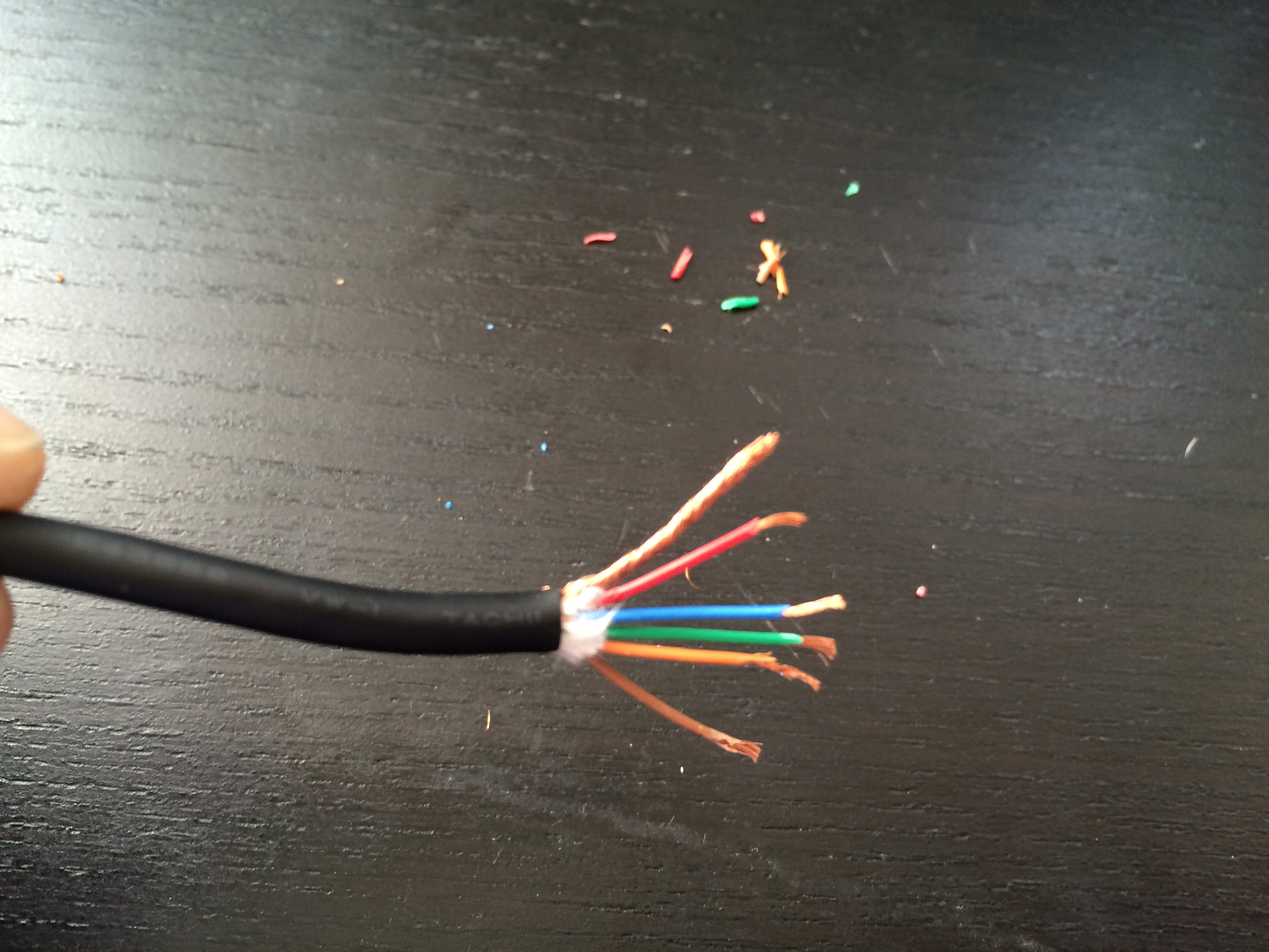
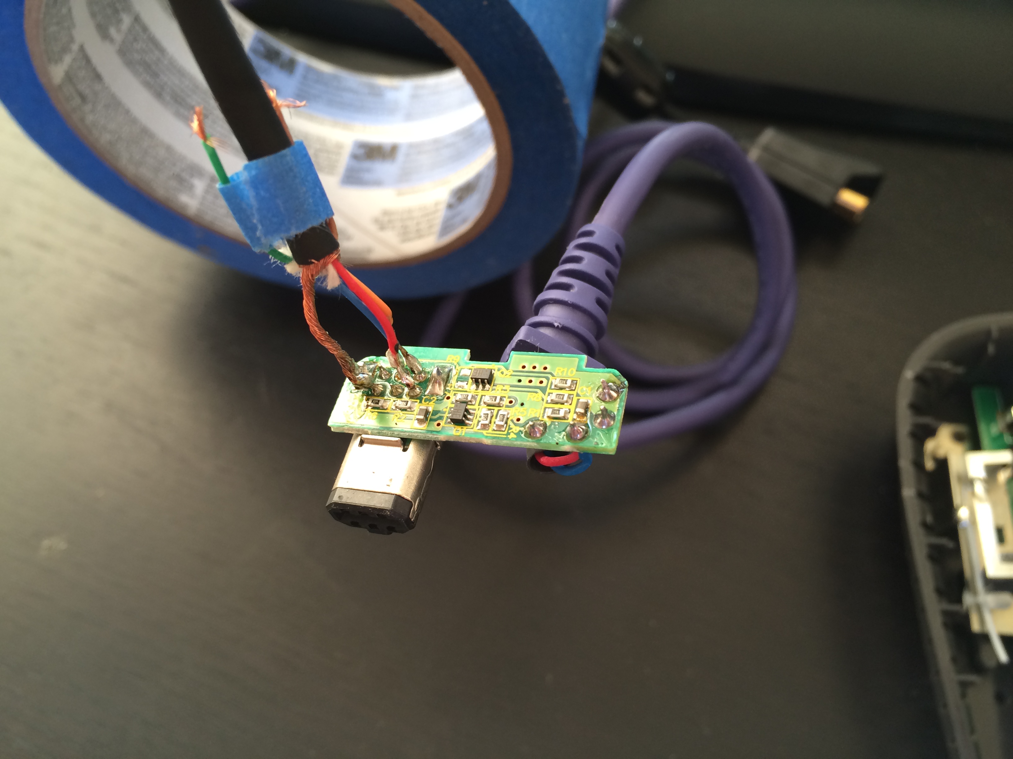
The first warning sign that I shouldn't be attempting this mod comes from my shitty pocket knife splicing job.
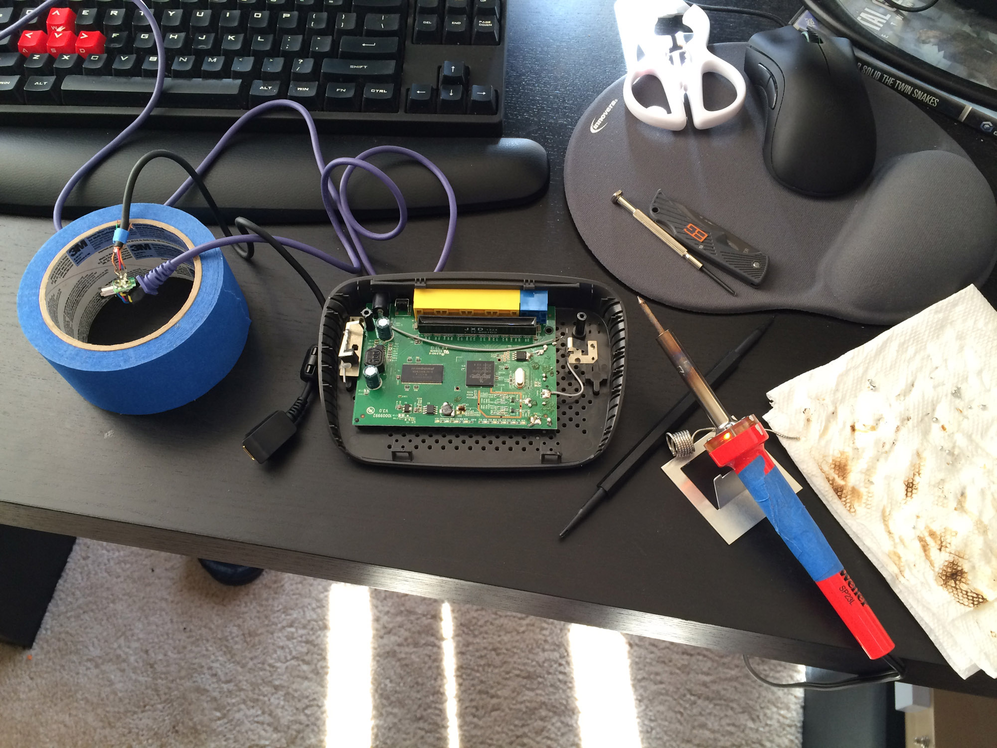
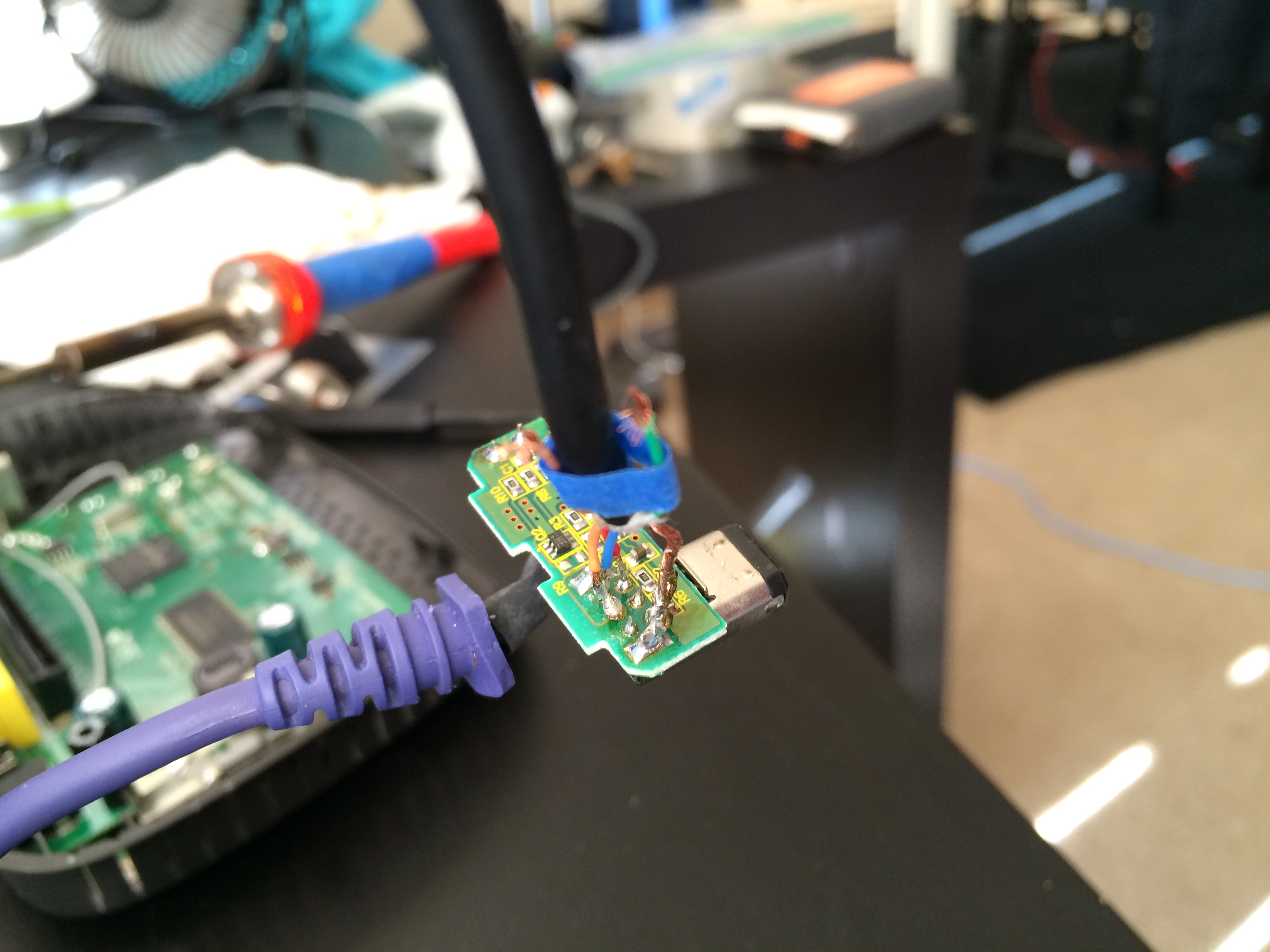
Next up was my makeshift workstation where I practiced soldering for all of 10 minutes on an old router I sacrificed to the cause.
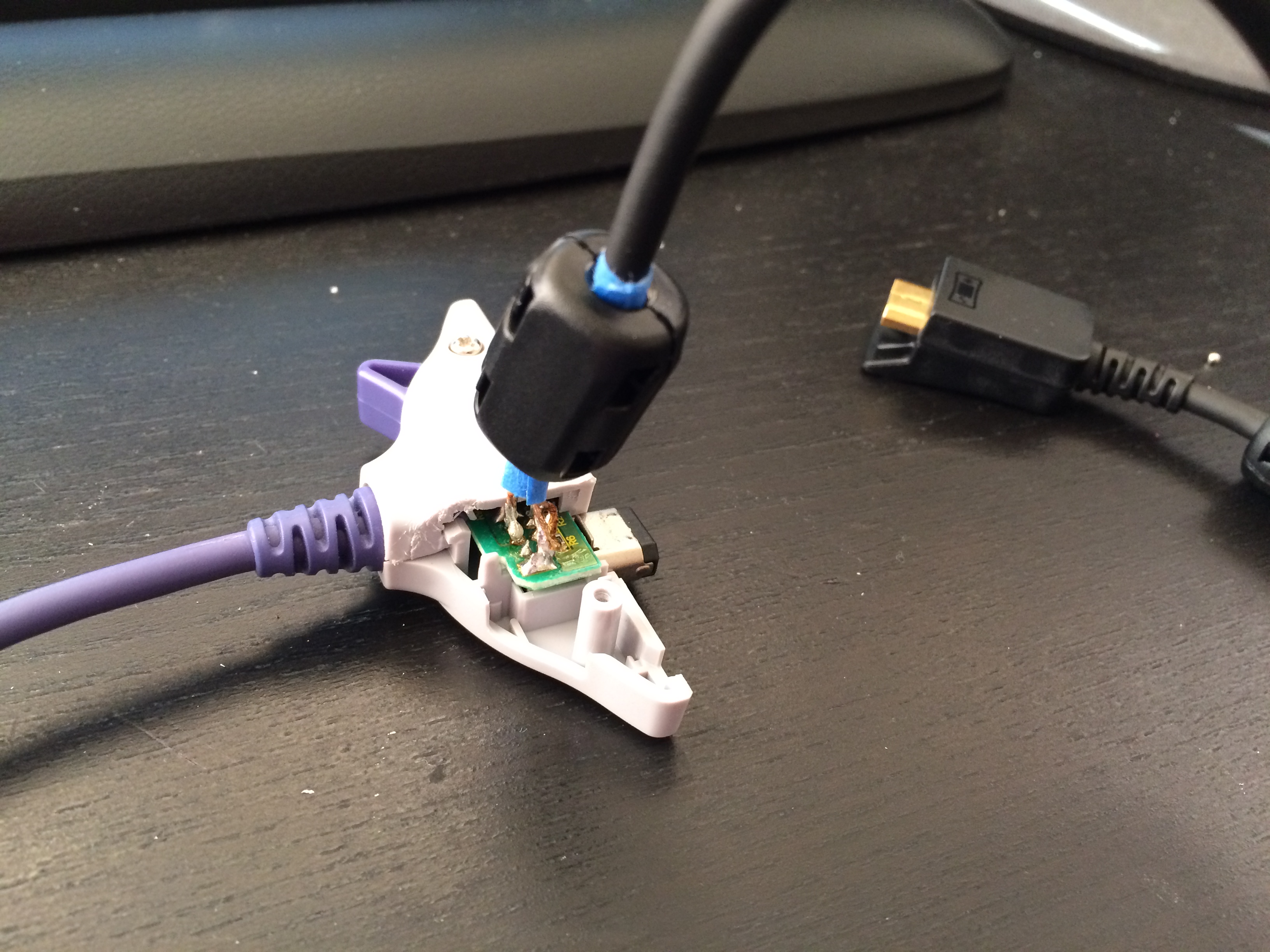
Prepare yourself, for you are about to witness the worst soldering you have ever seen in your entire life.
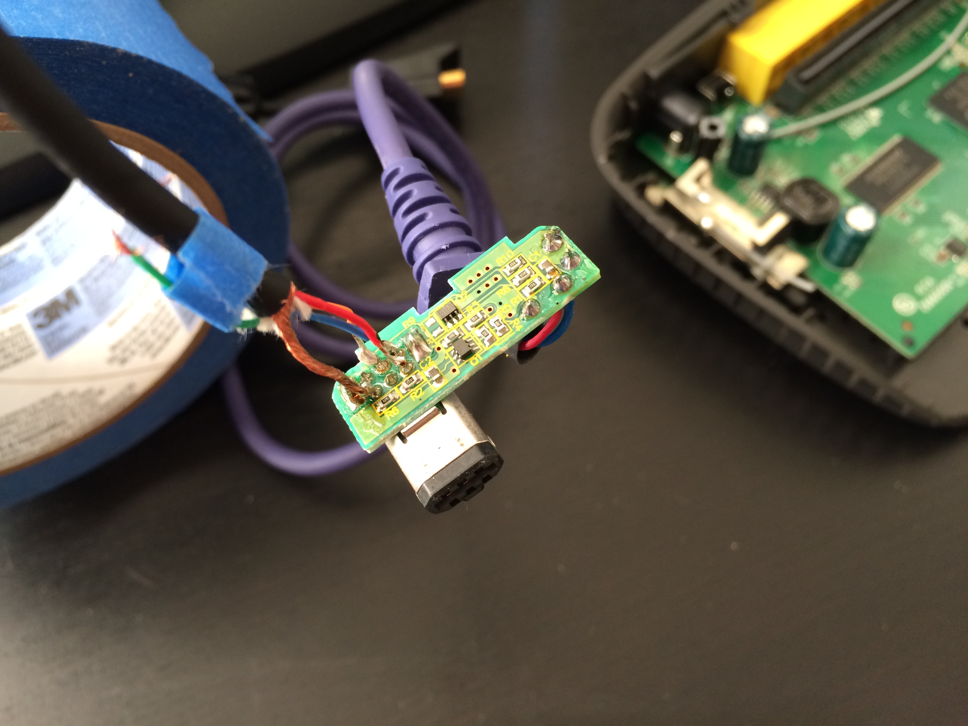
I'm not sure if my soldering iron is just shitty (it's this $20 from Amazon) but this is like 2+ hours later...
At this point I was like, " it, let's just see what happens."
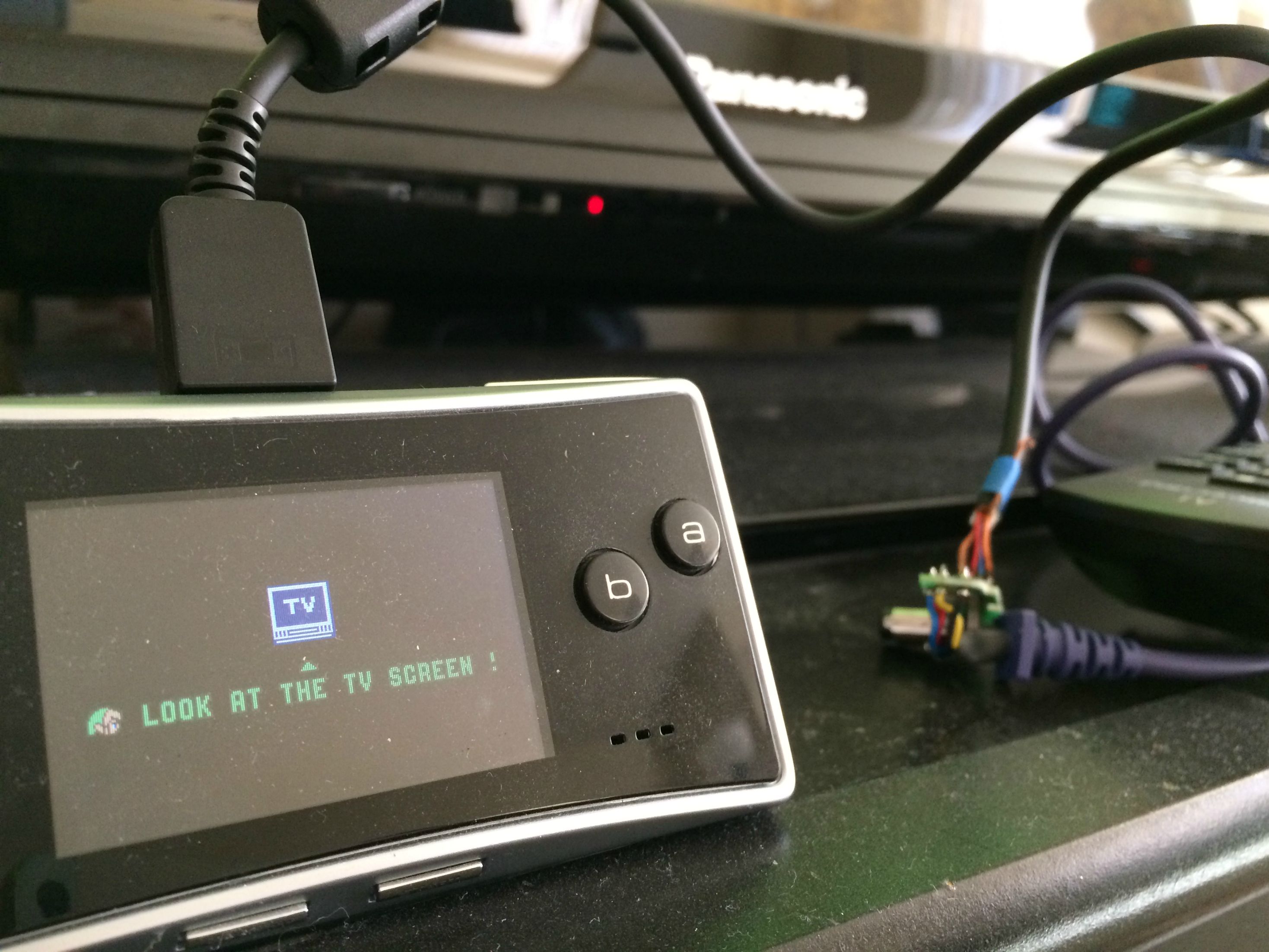
Holy shit, it worked!
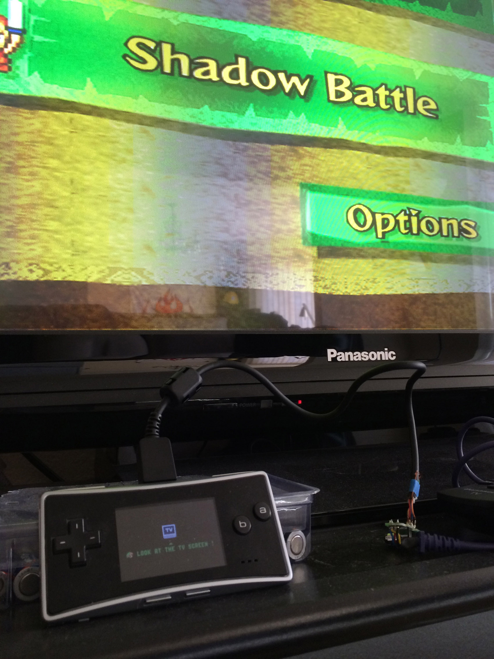
I still need to create a better housing, but for now this'll do. Maybe a good candidate for any of you with 3d printers (*cough* if someone wants to print one for me in exchange for $$$ *cough*)
I hope you enjoyed my deep dive into soldering and maybe this'll inspire some of you to go out there and give it a shot! Now time for some Four Swords!!
EDIT: Here's an album of all the images.
So, I decided to attempt this mod with little hardware knowledge (I'm a software engineer by trade) and without having ever soldered before.
I followed the steps from the OP but I used this link instead because the OPs images were broken, but seeing as the OP was posted 10 YEARS ago I guess it's understandable. =P
I happened to already have an original GCN to GBA cable, but I had to order the GBM to GBM link cable. This is the one I bought on eBay (in case the eBay link ever goes down, this is what it looked like).
The first warning sign that I shouldn't be attempting this mod comes from my shitty pocket knife splicing job.
Next up was my makeshift workstation where I practiced soldering for all of 10 minutes on an old router I sacrificed to the cause.
Prepare yourself, for you are about to witness the worst soldering you have ever seen in your entire life.
I'm not sure if my soldering iron is just shitty (it's this $20 from Amazon) but this is like 2+ hours later...
At this point I was like, "
it, let's just see what happens."
Holy shit, it worked!
I still need to create a better housing, but for now this'll do. Maybe a good candidate for any of you with 3d printers (*cough* if someone wants to print one for me in exchange for $$$ *cough*)
I hope you enjoyed my deep dive into soldering and maybe this'll inspire some of you to go out there and give it a shot! Now time for some Four Swords!!
EDIT: Here's an album of all the images.
Last edited by a moderator:
Dunnymeister
CAG in Training
Nice work Pawl! I'm looking into doing this mod myself, except with a crappy third party GBAGamecube cable. I'm a software engineer too, so your success gives me some hope I can pull it off
bread's done